
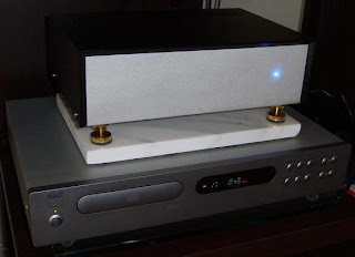
This is Mark's build of a simple and inexpensive 12AX7 tube preamplifier kit from Silicon Chip magazine. What makes this kit inexpensive (and interesting) is that power comes a switch mode power supply, which is fed from a 17 volt DC wall wart! To silence the skeptics of a switch mode power supply in a tube circuit, Mark has completed a number of measurements on the power supply as well as the preamp. Mark's modifications to the preamp kit include the addition of snubbers and upgraded capacitors. The end result is a simple DIY tube preamplifier that sounds great and will keep some money in your pocket for your next DIY Audio project.
 For more detailed information about Mark's latest project, see the project page, a DIY 12AX7 Tube Preamp kit.
Related Posts:
- Bruce's DIY 12AX7 Tube Preamplifier Kit
What's Playing: Pearl Jam - Glorified G
looks interesting.
ReplyDeletehow is the B+ generated?
That does look like an interesting little kit. Normally the B+ would come from a high voltage transformer 250+ volts. This looks like is takes DC from a wall adapter into a switching power supply which steps it up to high voltage. You don't see a switching supply with tubes very often, but the measurements look good.
ReplyDeleteAs anonymous has hinted the 17VDC from the wall wart is first regulated with a 7812 chip. Then a TL494 switch mode controller drives a MTP6N60E FET which supplies 33Khz AC to a hand wound pot core tranformer. The high volateg output is rectified by a single UF4004 diode which pumps a 10uf 450V cap.
ReplyDeleteThere is a feed back network which goes back to the controller chip to ensure the voltage is held constant. You can make a small adjustment of B+ via a trim pot.
Siganl to noise for the preamp is -81db and THD remain under 0.2%. In the artical which came with the preamp it is stated that there is a little low noise "fizzle" as a result of the switchmode 33Khz operation.
There is no buzz or hum in the speakers from the preamp. On my 10Mhz CRO I could find no noise on B+.
I modified these preamps, added 2 additional channels, an LED warm up/running power status backlighting, and time delay circuit and made a +260V car tube preamp. Very interesting!
ReplyDeleteThe original switching power supply design was not stable until I discovered a missing component in the schematic. But had to build a larger SMPS anyway for running 4 of these preamps.
The 220nf cap is way too small for driving the input impedance of SS amps, drving 10k it will have a 3db point of about 75hz. By connecting the 680nf feedback cap AFTER the 220nf cap it will keep a constant output amplitude over the whole bandwidth. The other option is to increase the 200nf cap for a 2u cap.
ReplyDelete