Showing posts with label solid state. Show all posts

12 April 2010

Hybrid Headphone Amp - 12AU7 Tube / IRF510 MOSFET


Rogers has improved upon his 12AU7 (ECC82) Tube / IRF612 MOSFET Headphone Amplifier project from August 2008 with a new version, the NP-100v12, a DIY 12AU7 (ECC82) Tube / IRF510 MOSFET Headphone Amplifier.  The 12AU7 / IRF510 headphone amplifier is powered from a rechargeable 12V sealed lead acid (SLA) battery which makes this an ideal project for novice builders as they don't have to worry about the high voltages typically associated with vacuum tubes.  The headphone amplifier circuit is very similar to the previous build utilizing a  single 12AU7 (ECC82) vacuum tube for the voltage gain stage which is followed by a IRF510 MOSFET follower stage which supplies current to drive demanding headphones.  IRF610, IRF611 or IRF612 MOSFETs will also work in this circuit.  The main difference between the updated headamp and the the original version is that a LM317 regulator (used as a constant current source (CCS)) is used in place of the load resistor to bias the MOSFET follower into class-A operation.

12AU7 Valve / IRF510 Mosfet with LM317 CCS Headphone Amplifier
12AU7 Tube / IRF510 MOSFET Headphone Amplifier
Included in the project documentation are printed circuit board (PCB) images and Eagle circuit board files so builders can easily make their own PCB for this project.  Being a fairly simple circuit, one could also easily build the headphone amp point-to-point on a 750 hole protoboard.  This simple headphone amplifier can be built for about $40-50 or less if you recycle parts and and enclosure.  For full details of this headphone amplifier, see the NP-100v12: DIY 12AU7 (ECC82) Tube / IRF510 MOSFET Headphone Amplifier project page.

More DIY Headphone Amplifier Projects:

What's Playing: The Beatles - Love

11 May 2009

DIY Lightspeed Passive Attenuator

Alps Blue Velvet, Bournes, TKD, Alps Black Beauty, DACT Stepped Attenuators ... If you are familiar with some of these names, you likely have an interest in high quality passive attenuators and you should continue reading. The noted items have a few things in common - first off, they are potentiometers that are often used as attenuators or volume controls in audio equipment. As a volume control, they also have another thing in common - they all used some form of "contact point" to attenuate audio signals. In the case of a potentiometer, this is typically a "wiper" which slides along a conductive material forming an adjustable voltage divider. If you are passionate about audio reproduction, you are fully aware that these "contacts points" can be the source of unwanted noise. Now it certainly does not make sense to spend money on high quality interconnect cables only to run the signal through a dirty potentiometer that you infrequently spray with with a contact cleaner like Deoxit.

When people talk about the "sound of capacitors" someone will inevitably say that the best sounding capacitor is "no capacitor" - that is if it can be eliminated. So following that principle, one could argue that the best sounding attenuator is one with no contact points in the signal path. Enter the Lightspeed Passive Attenuator.

The Lightspeed Passive Attenuator uses optocouplers to establish the level control and this is done with no "contact points" through the attenuator. The optocoupler is a LED and Light Dependent Resistor (LDR) is one housing. The operation principle of the Lightspeed is simple - by adjusting the intensity of the LED you can change the resistance of the LDR. By using a series and shunt combination of matched optocouplers the attenuator produces a constant input and output impedance, regardless of where the voltage control setting is. Hmmm, an attenuator with constant input / output impedance and no contacts points - great idea!

Lightspeed Passive Attenuator
Uriah has put together a detailed set of instructions to build a DIY Lightspeed Passive Attenuator. I've built one of the attenuators for myself (photo below) and I think it's great! It is a remarkable improvement over all the passive potentiometers that I have tried. The attenuator is very simple to build, so if you have an interest in higher quality volume controls take a look at the instructions.


The attenuator design could easily be scaled upward to include support for multiple channels and used as an effective way of controlling several of channels for a Home Theater setup. For full information, see the DIY Lightspeed Passive Attenuator.

What's Playing: Marta Gomez - Canta

08 February 2009

Jean Hiraga's Super Class-A Amplifier

Dan has completed a follow-up project to the Jean Hiraga - "Le Monstre" 8W Class-A Amplifier that he built back in July 2008. Impressed with the result of the 8W Hiraga, Dan set his sights to another Jean Hiraga design - the bigger "Super Class-A 30W" which also had previously appeared in the French magazine "L'Audiophile".

Jean Hiraga Super Class-A Amplifier
The original driver transistors were used, but seeing that the original power transistors are no longer available, Dan opted for Toshiba 2SA1943 and 2SC5200 transistors. The new transistors allowed the use of a higher rail voltages (35V vs 24V), resulting in a measured power output of 58W of Class-A power.

Jean Hiraga Class-A Amplifier PCB
The amplifier enclosure was constructed using aluminum channels and plates. As one would expect with a Class-A amplifier delivering this much power, the heat sinks are huge and so is the power supply (500VA transformer and 1.2 Farads of filter capacitors.

Jean Hiraga Super Class-A Amplifier
Dan reports good sonic results from this amplifier. "Jean Hiraga's deceptively simple and pure circuit topology once again shines through. The sound seems effortless and gives the impression of a much higher power amplifier yet still being able to produce all the low level details, the sound which Class-A is renowned for."

For full details of Dan's project, see the Jean Hiraga's Super Class-A Amplifier project page.


Additional DIY Solid State Audio Projects:

What's Playing: Sarah McLachlan - Adia

05 August 2008

Hybrid (12AU7 / IRF612) Headphone Amplifier

Over the past few years, headphones have come long a long way. For $70 to $150 you can get a great sounding pair of headphones. Best of all, headphones allow you to get right into the music anywhere you are and you do not have to worry about annoying things like room modes and reflections. And for you do-it-yourself (DIY) audiophiles, there are also a number of great DIY headphone amplifier projects that you can choose from. Here are the details for Rogers' low voltage 12AU7 tube hybrid headphone amp.
12AU7 Tube / IRF612 Mosfet Headphone Amp
Vacuum Tube / Mosfet Hybrid Headphone Amp
Rogers has put together a very simple hybrid headphone amplifier for use with 32 ohm Grado SR125 headphones. His hybrid head amp uses a vacuum tube voltage gain stage which feeds a MOSFET follower output stage. The tube is a the 12AU7 (ECC82) and the MOSFET is an inexpensive IRF612. The IRF612 is configured in a typical single-ended class A circuit using a passive constant current source (CCS).

What's best about this project is the power supply.
Both the 12AU7 tube and IRF612 MOSFET are set up to operate at low voltage (~12-13V). Power for this project is supplied via an external switch mode power supply (SMPS). All of the project parts are readily available and one can easily put together one about $40. Rogers has reported very good results from this very simple project. For full project details, see the 12AU7 Tube / IRF612 MOSFET Hybrid Headphone Amplifier Project.

Related Posts:

What's Playing: Tom Petty - Wild Flowers

30 June 2008

DIY Class A Headphone Amplifier

The computer sound card just didn't cut it when it came to driving my 32 ohm Grado SR80 headphones, so the need arose for a decent desktop headphone amplifier. Lately I have been reading a lot about Class A amplifiers and have been eager to try one, so a small and simple Class A headamp seemed like a logical first step in this direction.


The circuit is a simple single-ended amplifier with an active load. An inexpensive IRF610 MOSFET is used as the output device and a LM317 voltage regulator is configured as a constant current source (CCS). The power supply is a regulated wall wart which works very well and there is no hum. For the enclosure I used a dead external CD-ROM. This worked out very well as it will reside on my desk at work. I'm sure everyone will be wondering why I have an old external CD-ROM hooked up to a new laptop!


The results were very good. Despite the simplicity of the amplifier circuit it sounds surprisingly good. For more details, photos and a schematic, see the DIY IRF610 MOSFET Class A Headphone Amplifier Project page.

Related Posts:

What's Playing: The Farrell Bros. - Career Opportunities

12 January 2008

DIY 8W Class A Amplifier

Dan in Australia has put together a great looking Class A amplifier. The circuitry of the amplifier is based on the popular article "Le Monstre" by Jean Hiraga which appeared in Issues 27, 29 and 31 of the French Magazine l'Audiophile.

Dan used the board layout, transistors and JFETs documented in the articles. However, instead of using a capacitor bank and battery setup, this amplifier uses regulated power supply.

The photograph below shows an early version of the amplifier.

Jean Hiraga The Monster DIY Class A Amplifier Project
Dan later added additional capacitance and rearanged the wiring as shown in the photo below.

Jean Hiraga Le Monstre DIY Class A Amplifier Project
Dan reports that he is very pleased with the sonic performance from this amplifier. For additional information about this amplifier project, see Jean Hiraga's Le Monstre - DIY Class A Amplifier Project.

Related DIY Solid State Audio Projects:

04 July 2007

DIY Class A Mosfet Amp

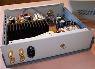
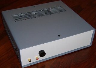
Shown below is Jochem's first DIY Audio Project, a build of Mark's DIY Class A 2SK1058 Mosfet Amplfier project.

DIY 2SK2221 MOSFET Amplifier
Jochem's build of this very simple Class A Mosfet amplifier uses the 2SK2221 Mosfet instead of the 2SK1058 that Mark used. The power supply has been modified slightly and uses two large toroid chokes for good filtering. The photographs below show the finished amplifier.

Single Ended Class A Mosfet Amplifier
DIY Class A MOSFET Aplifier Project
Jochem is very pleased with the results of his first audio project and is looking forward to completing more DIY Audio Projects in the future.

For additional information, pictures and schematics, see the complete project writeup of Jochem's DIY Class A 2SK2221 Mosfet Amplifier Project.

Related Post:
What's Playing: Blancmange - Don't Tell Me

18 November 2006

Class A MOSFET Amplifier

Another one of Mark's projects has been added to the DIY Audio Projects web site. This time, Mark has put together a very simple MOSFET amplifier that he has fashioned after a single-ended (SE) tube amplifier.

DIY Class A MOSFET Amplifier
The amplifier uses a single MOSFET and the results are a very simple Class A SE amplifier with a low parts count. As with all of Mark's projects, the enclosure work is top notch.

 Single Ended Class A MOSFET Amplifier
For more information and photographs about this project, see Mark's DIY 2SK1058 Single Ended MOSFET Amplifier Project page.

Related Projects:
What's Playing: Red Rider - Walking the Fine Line