The schematic below shows the tube amplifier circuit (click to enlarge). The items in red are the changes that are required for the conversion to UL mode.

To change the output section to UL the screen grid resistor (R107, 1k) was removed and the UL tap (tap 3) from the Edcor audio output transformer (OT) is wired directly to the screen grid (pin 10). Other changes I made to the amplifier circuit were to replace the input capacitor C101 (and C201) and the coupling capacitor C102 (and C202) with 0.22 uF metalized polypropylene types. This helps improve the bass response slightly.
The power supply schematic is shown below (click to enlarge). On the power supply I made the following changes which are shown in blue on the schematic. 0.01 uF polyester capacitors across the rectifier diodes. 0.1 uF polypropylene capacitors across all the electrolytic capacitors. One additional 100 uF electrolytic capacitor in the power supply.


Tube Amp Construction Notes
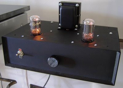
I wanted the amp to look cool (very black) and minimalist with its gold connections hidden and all hardware neatly tucked under a black enclosure. Two coats of Epoxy Enamel spray paint was used on the case once all drilling had been completed.

The amp is designed to deliver music well, to be unassuming in appearance and have a high wife acceptance factor (WAF). The OTs are slung under the top plate where the power transformer is mounted. Once again the power transformer and the OTs are rubber mounted. Multi-core shielded cable is used to connect the rear gold insulated RCA connectors to the 50k potentiometer and to the printed circuit board (PCB). The power switch was conveniently placed at the front of the amp and a captive power cord was used.
The potentiometer should be connected to the signal ground. Also keep the chassis earth and signal earth separate. Use the shielding on the input wiring to distribute the earth to the input RCA connections, potentiometer and PCB.

6T9 Tube Amp Measurements
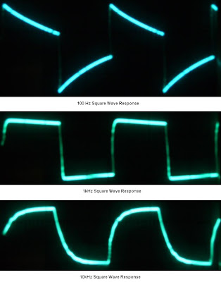
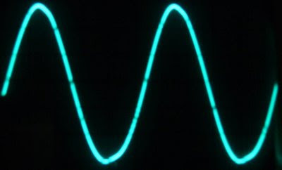
The photographs below show the sine and square wave response of the amplifier. There is little to no change in the response compared to pentode operation.
Sine Wave Response - 1kHz @ 6.2V P-P, 8-ohm load
6T9 Tube Amp Sound
I played the new amp without NFB and with to determine the best sound. I found the amp sounded much better with NFB. The UL version of the 6T9 tube amplifier sounds better than the Pentode version. Because so many of the components are the same in both amps the improvement in sound is likely due to the UL operation mode.
Mark Houston

Additional 6T9 Tube Amplifier Links


You show a 6.2Vp-p output into an 8ohm load. This is approximately 600mW into the load. I am assuming that this isn't full power. Do you have any estimates of maximum clean output power and input sensitivity for this UL version?
ReplyDelete4.5 Watts you mean, right? Power = Voltage x Voltage / Resistance.
ReplyDeletePower calculation must use RMS voltage...(6.2Vp-p / 2) * .707
ReplyDeleteWhat make/model xformer was used in the power supply?
ReplyDeleteIt looks like the same power transformer from the other 6T9 project build: http://diyaudioprojects.com/Tubes/6T9-Tube-Amp-Kit/
ReplyDelete"I used a Hammond 369JX power transformer and Edcor XSE15-8-5K for the output transformers (OT)"
Anon
Deleteit really does not matter what PT you use or manufacture. Use a PT in the range of 300-300 HT and 6.3v at 2a for the heaters. Use solid state rectifiers like the 1n4007, either in a full wave and full wave center tap config. In a full wave bridge config use the listed Caps for values. In a Centertap config use a larger cap config by 20%. But these 6T9 tubes don't req., very much current. At max vol expect 60-80ma current. So even a secondhand PT would be fine. vince
That's fantastic! It would have been great if you were able to make a sound demo for it. If I only knew how to make one of these, I would settle for a DIY tube amp. How much do these tube amps sell these days. How are their prices compared to a solid-state amp?
ReplyDeleteI built this project and it sounds much better than I expected... very musical and crisp, yet mellow.
ReplyDeleteI do have one comment and two questions:
Comment: Using diodes to make the rectifier, the turn-on current is high enough to blow 0.75A slo fuses... I moved to 1.0A and all is fine.
Question1: The metal chassis near the tubes get hot... like real hot. Hot enough to melt the epoxy I used to glue some spacers inside the chassis. Is that expected? Is there better glue to use?
Question2: After an hour or so of use (first time) the gain seemed to decrease and a hissing noise seemed to increase over time. I assume related to the heat... as I turned it off, and later it sounded fine.
Hi Jim,
ReplyDeleteBased on your description, you may have a heat build up problem. As the temp rises, the resistors will change in value and that could be the source of your problems.
I would suggest by improving ventilation through the chassis. Drill holes in the top plate to exhaust the heat and holes in the bottom to take in fresh are.
Hope this helps.
I built this amp, and when it works it sounds very nice. However, I do have an issue. It eats fuses like candy. The only deviation i made from the schematic was for the power transformer. I used an Edcor XPWR065-120 for the power transformer. It has the same voltage IO, but higher current capability. I assumed (maybe incorrectly) that since the output xfrmr voltages were the same, then the current would be dictated by the circuit connected and not related to the xfrmr itself. Anyway, I've used even 5A fuses and even they blow (usually at turn on).
ReplyDeleteAny help would be appreciated... info or even the best way to debug the issue.
Thanks,
Jim
Jim
Deleteit sounds like you need to contact Edcor and ask for technical support. It's not the DIY amp here that is blowing your fuses. I think it's the Edcor transformer and use slowblow fuses. vince
Hi Jim, try using a slow blow fuse.
ReplyDeleteCheers
http://www.thetubestore.com/ For your 6T9 tubes.
ReplyDeletehttp://www.ebay.com/itm/6T9-GE-USA-Compactron-New-Old-Stock-Tested-BIN-15-/222513992624? for your 6T9 tubes.
ReplyDeleteI wish there was a parts list or BOM. The posted pictures here on these web pages don't show and shows just a blank image. vince
ReplyDeleteI don't quite understand UL configurations from Pentode configs. vince
ReplyDeleteI have tried just now to Email the author of this project and i am unable to contact him (email was returned deliverable). If i could get the pictures of the Schematic and power supply schematic that would be very helpful because they come up here on this page and blank images! Vince
ReplyDeleteOoops Undelivered(user not known)i mean(typo) and was returned back to me. Any-help in this matter would be most greatly appreciated. Vince
ReplyDeleteCould you clarify the use of the 0.1uF caps across the PSU caps? I do this for all kit with RF floating about, but don't understand the benefit for audio equipment. Thanks.
ReplyDeleteI bought one of these off eBay. I added a choke, put mundorf Evo oil coupling caps and the UL upgrade as well. Sounded pretty good, then I put jumpers in place of the input caps. The difference was astounding. The cymbals sound as though they were in the room. Got rid of the "muddy and dark" sound. Highs really sparkle, just crisp and clean. I am running a preamp so DC in the inputs are a non-issue. Thanks for the info.
ReplyDeleteI’m ready to build this amp but I’d like to use tube rectification. I have a strong 5u4 tube that I’d like to incorporate into the build. Anyone try tube rectification for this amp?
ReplyDelete